Technova - Technova
AI Solutions • Data Center • Power System

智能科技 Technova

I am

About me

Hello

I'mLeon Song

Electrical Engineering Trainer & System Engineer

I hold a Ph.D. from Harbin Institute of Technology and completed postdoctoral research at Tsinghua University. I previously worked for two global technology leaders, Emerson and Huawei, where I gained extensive experience in power electronics, power systems, and data center power distribution solutions.

We specialize in the design and development of customized engineering solutions, including: Power Supplies • Solar Power • Wind Energy • Transformers • Motor Drives • Power Distribution Systems. Whether you have an innovative idea or a specific technical requirement, our team is committed to delivering reliable, efficient, and cost-effective solutions tailored to your needs.

Our partners and manufacturing resources are based in Shenzhen. I lead the development of an AI-driven platform for electrical engineering.

Engineering Experience

Emerson Network Power

1999-2011

Positions Held:

R&D Engineer | Project Manager | System Engineer | General Manager

Obtained multiple patents in related fields.

Key Responsibilities and Achievements:

• Worked as an R&D Engineer designing advanced power converter systems, with expertise in high-performance power electronics, converter topologies, and power conversion system design.

• Led the development of industrial power supply systems, serving as both an R&D Engineer and Project Manager throughout the full product lifecycle—from concept development and system design to prototyping, testing, and production.

• Managed renewable energy R&D projects involving the research, development, installation, testing, and maintenance of 690 V / 1.5 MW doubly-fed and direct-drive wind power converter systems, as well as power distribution system design. Led the design and construction of an OSHA-compliant wind power inverter laboratory for system testing and validation.

• Served as a System Engineer responsible for the engineering, installation, construction support, commissioning, integration, and field deployment of medium- and low-voltage Variable Frequency Drive (VFD) product families rated from 220 kW to 8 MW (3 kV, 6 kV, and 10 kV). Provided on-site technical support for system installation, equipment setup, testing, startup, and field troubleshooting to ensure successful project execution. PMP certified.

Led the engineering and field implementation of medium- and low-voltage electrical systems, including motor control centers (MCCs), control panels, and industrial automation systems. Performed system-level modeling and simulation using Saber to support design validation and field performance verification. Led the planning, construction, equipment installation, and commissioning of an OSHA-compliant high-power VFD testing laboratory.

• As Head of the Pre-Research Department, led cross-functional teams responsible for technology scouting, and the development of next-generation products and systems. Oversaw departmental operations, including technology strategy, talent acquisition, performance management, budget planning, and long-term roadmaps.

Huawei Technologies Co., Ltd.

2011-2017

Positions Held:

Power System Engineer | Electrical Construction Engineer

Obtained multiple patents in related fields.

Key Responsibilities and Achievements:

• Served as a System Engineer (SE) responsible for the planning, design, installation, commissioning, and manufacturing support of 6 kV/2.4 MW Variable Frequency Drive (VFD) systems and related product families. Led the engineering and implementation of medium- and low-voltage power distribution systems, motor control centers (MCCs), electrical control panels, and industrial automation systems. Drove key technical improvements to enhance system reliability, cost-effectiveness, and overall product competitiveness. Also led the planning, design, construction, and commissioning of medium- and low-voltage VFD testing laboratories.
• Served as a System Engineer (SE) responsible for the engineering, installation, commissioning, maintenance, and technical support of 400 kVA Uninterruptible Power Supply (UPS) systems. Performed Failure Mode and Effects Analysis (FMEA), root cause analysis, and comparative technical evaluations to improve system reliability, maintainability, and field performance.

• Served as a System Engineer (SE) responsible for the engineering, installation, construction support, and commissioning of 2 MW data center infrastructure projects. Developed end-to-end technical solutions covering 35 kV substations, standby generators, transformers, medium- and low-voltage power distribution and switchgear, UPS systems, battery systems, PDUs, IT critical loads, and cooling systems. Prepared engineering drawings and construction documentation using AutoCAD, and provided technical support throughout installation, system integration, testing, and project delivery.

• Designed a 330 V DC / 140 kW electric motor drive system for an electric vehicle. Conducted competitive benchmarking analysis and developed system-level product design proposals and architecture.

• Served as General Manager and Team Leader, while also managing multiple key projects as Project Manager. Experienced in leading cross-functional teams, driving project execution, and overseeing end-to-end delivery.

iHOT medical physics consulting Co

2018-2022

Positions Held:

Electrical Test Engineer | Quality Assurance (QA)

Key Responsibilities and Achievements:

• Performed daily, monthly, and annual testing and calibration of clinical linear accelerators. Executed case-by-case QA testing, treatment plan evaluation, and medical physics planning support.

• Maintained a strong focus on quality assurance and system safety, with 3 years of experience in QA operations.

Technova Electrical Engineering

2023-2026

Positions Held:

Electrical Engineering Trainer | System Engineer

Key Responsibilities and Achievements:

• Technical training and lectures to engineers on power distribution systems, data center infrastructure, and renewable energy technologies.

• Supported development and evaluation of customized power electronics and micro-scale electromechanical systems for application-specific solutions.

WHAT CAN We DO

Power Electronics Design

Research & analysis of technologies for industrial, energy, and data center applications. Component selection, electrical calculations, circuit design, PCB layout, prototyping, testing, and technical documentation for power electronic systems.

Custom Prototypes

From concept to prototype, we provide customized engineering solutions for power supplies, solar power systems, wind energy systems, motor drives, and related power electronics products. No project is too small. We work closely with our clients to transform ideas into working solutions.

Pilot Production Services

We offer pilot production services for power supplies, renewable energy systems, motor drives, and other power electronics products. From engineering samples to pre-production units, we help clients verify designs, optimize performance, and prepare for commercial manufacturing.

Product Manufacturing

We support the manufacturing of custom power supplies, renewable energy systems, motor drives, and other power electronics products. Whether you require small-batch production or high-volume manufacturing, our focus remains on quality, reliability, and continuous improvement.

Custom Components

Design and supply of custom magnetic components, including transformers, inductors, reactors, and filters, as well as custom capacitors and other power electronic devices. We support both custom-engineered solutions and standard component sourcing for industrial, energy, and power conversion applications.

Customer Support

We are committed to providing responsive and reliable support whenever you need assistance. Whether you have technical questions, project updates, or service requests, our team is ready to help. Your success is our priority, and we strive to build long-term partnerships through exceptional service and support.

1236

Custom Power Supply

55

Custom Small Solar Power

110

Custom Small Wind Power

86

Small Motor Drive

Resources

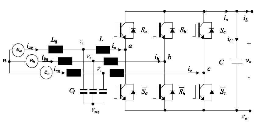
Wind Power Direct Drive Control System Scheme


Grid-side Inverter Control Scheme


1. Electric Circuit Model
2. Mathematical Model


3. Controlled Object
4. Control System Scheme


Motor-side Inverter Control Scheme

1. DQ Mathematical Model


2. Electric Circuit Model


3. Control System Scheme Model


4. Speed Sensorless Observer


Cascade topology-based medium voltage motor drive Technology


Cascade topology-based medium voltage motor drive (MVD) Technology


Key Players of MVD Industry


Topology Selection of 100A High Efficiency Rectifier

 
1. Topology Classification


lDirect three-phase systems
  Single-stage
             ZVS Three-phase single-stage isolated rectifier
  Two-stage
             Unidirectional
                       Two-level  
                                      Three phase Buck
                       Multi-level  
                                     Vienna Rectifier
            Bidirectional
                       Two-level
                                      Six-switch rectifier
                       Multi-level
                                       Neutral point clamped converter


lCombination of single-phase systems
            Line-to-line 
                                voltage input (Δ-Rectifier )
            Line-to-neutral
                                voltage input (Y-Rectifier)
                With stable artificial neutral point
        With controllable neutral point

                
2. Select Topology


    3. Candidate


lSingle-Stage direct three-phase systems
          ZVS Three-phase single-stage isolated PWM/LLC rectifier
lTwo-Stage direct three-phase systems
          Vienna Rectifier + three level full bridge LLC
          Three phase Buck 
          Six-switch rectifier 
          Three level Neutral point clamped (NPC) converter 
lCombination of single phase systems
          Δ-Rectifier 
          Y-Rectifier with stable artificial neutral point 
    Y-Rectifier with controllable neutral point


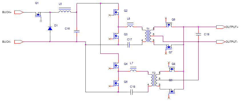
The DCDC Converter Circuit Design in Electrical Vehicle

The DCDC Converter Circuit Design in Electrical Vehicle


1.  DCDC  Converter Design- spec

Input voltage:                                210Vdc~410Vdc
Output voltage:                             14V1500W
Output voltage adjustable range:   12~16Vdc,  PWM signal control
Regulation:                                      ±1%
Start up overshoot:                        ± 5%
Transient response:                      1ms, 0%~50%~0%  1000A/s
                                                         0%~100%~0%  1000A/S
Ripple:                                          200mV
Efficiency:                                     92%
Protection function:                     Input under voltage: Automatic recover
                                                         Input over voltage: Automatic recover
                                                         Output under voltage: Automatic recover
                                                         Output over voltage: Latch
                                                         Over load/short circuit: Automatic recover
                                                         Over temperature: Automatic recover
Remote control:                              TTL level voltage

Fault alarm:                                     OC alarm

Mechanical outline:                      280mm×200mm×70mm
Weight:                                          3.6kg
Operation temperature:              -40~85 ℃
Cooling:                                         Water cooling ( water temperature: 75℃)
                                                          ( water press is from 0.02Mpa)
EMC:                                              CISPR 25, Level 4

Vibration:                                       QC/T 413-2002 3.12,   Not on the Engine in engine  
                                                       cabinet 
Protection:                                    IP66


2. DCDC  Converter Design- Circuit 


(1).             EMI stage:
                   Four common mode inductor: 2.1mH, R7K, T25X15X10, 1.2mm, 23T


(2). Buck+ open loop interleaved LLC
   Buck: Mosfet: 20N60,  Diode:R1560
  Inductor: 2X56uH, CS234090, FeSiAl, 1.0mmX3, 20T
  UC2843  IRS21834
  Switching frequency:   100KHz


(3). Open loop Interleaved LLC
    Primary Mosfet: IRF38N20,  Synchronous Rectifier: IRF3805
    Lm: 18uH,  Lr: 2.6uH,  Cr:39nF
    Lr:  2.6uH, PQ26, PC95, 0.25X3.5X4, 3T
    Transformer: ER30, PC95, Primary 4OZ PCBX2, 5T
    Secondary 0.2X4.5mm copperX6, 1T
    Output Capacitor: 10uFx17
    Switch frequency: 300kHz  


(4). Auxiliary Power Supply
      Transformer: EFD20, PC40
      Mosfet:          9R1K20
     Control IC:    UC2844
     Switching frequency: 130KHz


Calculation of Inductance of chokes to be used for the paralleling of the Inverters

For the calculation of the Inductance of the chokes to be used to parallel the two inverters, we take into consideration the following two possibilities:

1. The corresponding parallel arms +ve & -ve are connected directly to one another (i.e. using busbars) as a result of which the inductance at the input is negligible.

2. The corresponding paralllel arms +ve & -ve are both connected to the output of the bridge rectifier as a result of which the inductance of these connections must be taken into consideration.

In the diagrams, for clarity, only one arm of each inverter has been shown and the possible connection of the DC busbars at the inut of each arm. It must be understood that for the entire system, there would be 3 such arms per inverter, giving therefore the 3-phase output.

Case 1

Direction connection of DC Inputs of paralleled Inverters


Here we have,

maximum value of Vdc = 850V

maximum delay between switching OFF of one TOP IGBT and switching ON of one BOT IGBT, Dt = 125 ns (i.e. the maximum possible time delay between the control pulse being received at the IGBTs and the IGBTs switching as a result)

say, maximum allowed DiSC = 10 A

Therefore,

Lac = 850 /(2 x 10)x 0.125 µH
       = 42.5 * 0.125 µH
       = 5.3125 µH
Lac = approx 5 µH

Case 2
Connection of Inputs of paralleled Inverters to Input bridge rectifier.


In this case, the additional inductance at the outputs of the bridge recifier will serve another purpose i.e. to smoothen the ripples in the output of the bridge circuit.


800kVA UPS Topology & Load Sharing Control Algorithm


Test result (1+1 multi-module system)


       CH4-System Voltage                    CH3-MOD#1scope_6

Nonload

THDu=0.39%/0.36%/0.35%  

Circulating current=4.44A


 scope_8


100kVA rectifier load (Acf=3)

THDu=1.62%/1.59%/1.56%

Current Unbalance Degree =0.72%


Current CH2-MOD#2 Current

scope_7


100% resistive load

THDu=0.45%/0.50%/0.37%

Current Unbalance Degree =1.53%

 scope_9


100% standard rectifier

THDu=1.34%/1.20%/1.31%

Current Unbalance Degree =1.12%


Events Recap

SHENZHEN ECOWATT POWER CO.,LTD

A national high-tech enterprise that integrates product Research and Development, manufacturing, sales and service Industrial ups leaders.

Cooperation & Alliance

CEO: Lihua Xie, Ph.D

New Power Electronics Product Development

Design and develop new smart large power charging technology and product for industrial manufacturing.

A new company is building by Heng Yu.

Team Leader: Heng Yu

New Power Electronics Technology Pre-Research

New flexible universal multiple levels topology for small, large power and low or high voltage in renewable energy.

Sustainable energy

Engineer: Leon Song

Leon Song
Xia(Lily) Yu
+1 916-793-0676
(Texting Only)
Wechat 微信 ID
Leon_Song_PhD

SEND ME A MESSAGE